The Pummer circuit presented on the Solarbotics website is a nice beginner project. However, there is no detailed explanation of what the components do and there are multiple contradictory circuit diagrams on the page. Here you'll find a tested version, a full description how the circuit works and some hints how to make it work.
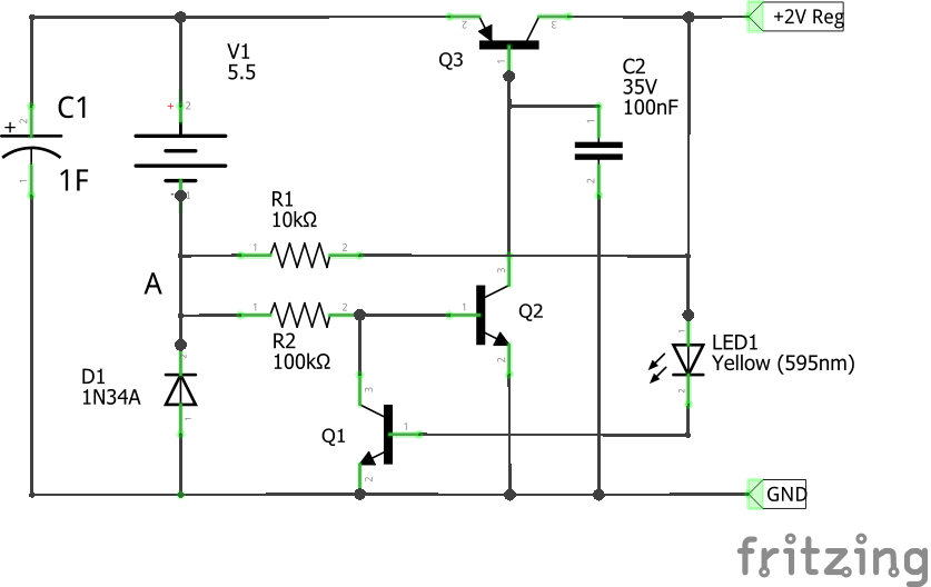
This circuit provides 2V regulated at night while it charges a 1F supercapacitor during the day.
While V1 produces about 5.5V during the day it charges C1 slowly. Depending on your solar cell, it will take a couple of hours. During this time, D1 priovides a 0.3V drop between the negative side of the solar panel and ground. Because of this, the wires between V1 and D1 (marked A) are actually slightly negative with respect to GND. This negative voltage is then applied at Q2's base, which forces that transistor to switch off. In this state, Q2 does not allow any current to flow through the base of Q3. Since Q3 is a PNP transistor (base current makes it turn on), it stays closes, and the 2V output stays low.
As less light reaches the solar cell, it produces less and less voltage, slowly going towards 0. However, since C1 is now charged, and D1 still drops voltage over it, making A slighly positive w.r.t. GND. This turn Q2 on, allowing base current to flow out of Q3. Now Q3 is on and voltage from C1 can flow out of the regulator.
LED1 is used to provide a reference voltage. The solarbotics pages mention using red LEDs to acheive 2V, but those usually provide a voltage drop of 1.8V. Yellow LEDs seem to be much closer to 2V and I recommend using one here. Measure the actual drop, since the value can vary quite a bit between different builds and soem kits from places like Amazon can have variation within the same batch. You can use other LEDs for higher output voltages, but be aware that this reduces how much you can discharge C1.
Once LED1 starts conducting, it provides voltage to Q1, which begins to conduct. This connects the base of Q2 to ground, forcing it closed. This in turn switches off Q3 and then LED1. Thus the loop Q3 -> LED1 -> Q1 -> Q2 is formed, which continues to oscillate around the reference voltage provided by LED1. C2 stabilizes this loop and removes some very high frequencies.
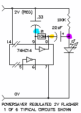
The purpose of R1 is not discussed in the original sources, and in the full pummer circuit it appears as a 100k resistor connecting the positive and negative terminal of V1. On the page showing only SIMD1, it is a 10k resistor between the negative terminal of V1 and the +2V output. In both cases R1 is a shunt resistor for V1, which modifies its I/V curve (see here), to collapse sooner (i.e. as less light falls onto the cell).
The configuration shown here (10k from V1- to +2V) has been tested and works. Due to R1 being connected on the output side, it is only functioning at night, when regulated voltage is provided. This seems to also provide some positive feedback for the regulator.
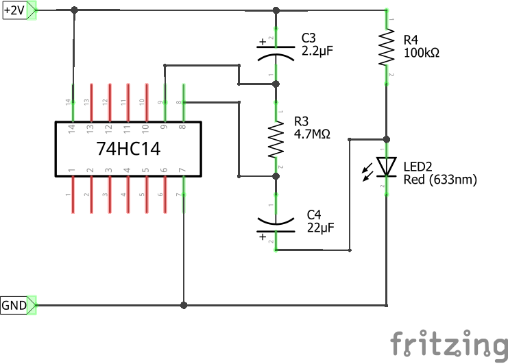
The full pummer circut is built around the 74HC14 IC, which contains six Hex inverting Schmitt triggers and it works well on 2V. These are used to build an oscillator, which periodically turns on the connected LED.
The Schmitt trigger (ST) acts as a binary comparator, which compares its input voltage to a positive and negative threshold. Based on this it transitions to a high or low output. Looking at the datasheet we get:
| Min | Typ | Max | |
| VT+ | 0.7V | 1.2V | 1.5V |
| VT- | 0.3V | 0.6V | 1V |
VT+ and VT- are given for an input voltage VCC of 2V. This means in general we can expect pin 8 to output low (0V) once the voltage at pin 9 goes above 1.2V and to go high (2V) once it goes below 0.6V. Note that the 74HC14 has an inverter after each Schmitt trigger, hence the "high when low" behaviour.
The oscillator can be found in The Art of Electronics (3rd ed.) on page 427 in Figure 7.5. When C3 is not charged, the trigger outputs 2V. These 2V slowly charge C3 via R3. Since C3 is connected to the input of ST, once the voltage at C3 exceeds VT+, the ST will go low. This causes C3 to slowly discharge, until it goes below VT-. Then ST outputs 2V again and the charge/discharge cycle continues. Hence C3, R3 and ST form an oscillator, which outputs a square wave between 0V and 2V into C4.
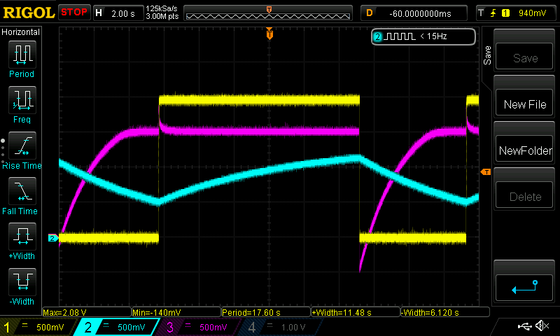
While ST outputs low, C4 charges to about 1.5V through R4. When ST goes high and outputs 2V that is in series with the 1.5V in C4, we get 3.5V, which is enough to flash the LED. The following figure shows oscilloscope traces of the described process. Briefly:
This page takes heavily from the listed sources, which are published under CC BY-NC-SA 1.0 and as such is republished under the same license. Circuits were designed by Wilf Rigter.
